November 3, 2026 / Studio Practice
Motion RC explained: how motion behaves in remote-controlled systems
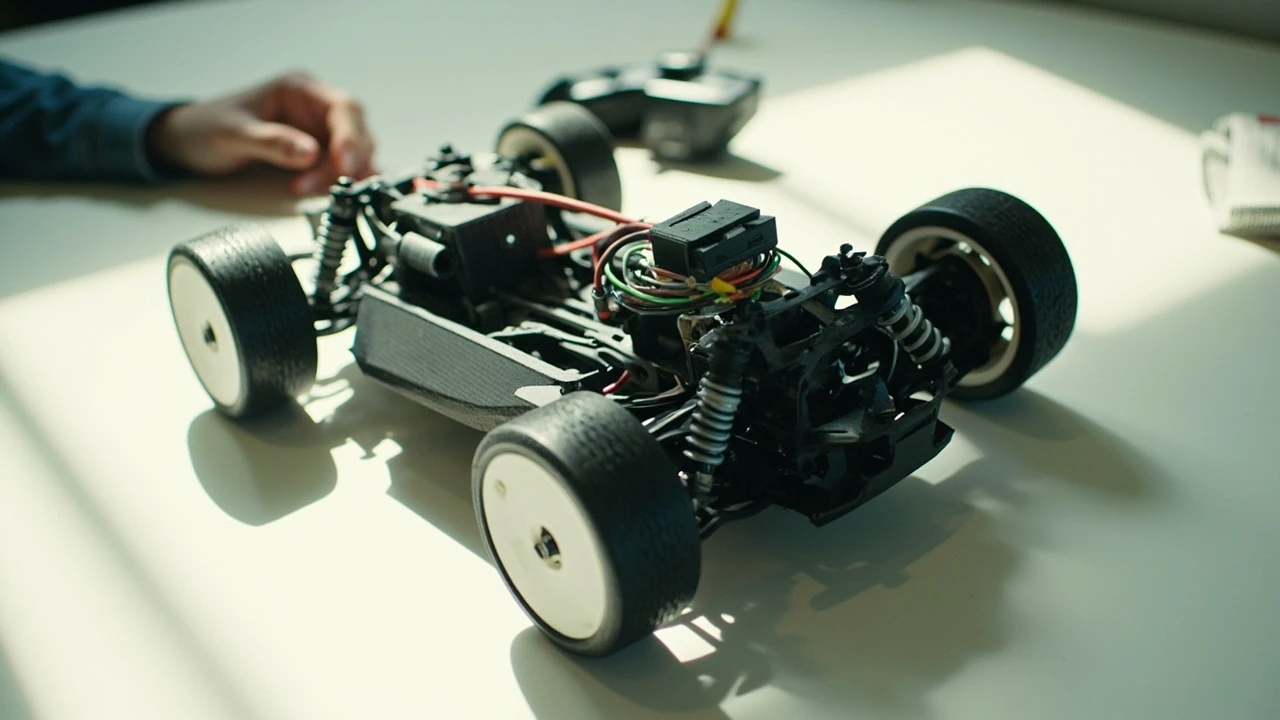
Motion RC: what the term actually means in remote-controlled systems
A driver watching a small electric car take a corner at speed is seeing the result of a chain of mechanical, electronic, and software decisions. The phrase motion rc is shorthand for the way movement is produced, transmitted, and controlled inside a remote-controlled platform, whether that platform is a car, a boat, a drone, a robot, or a submarine. Every such device translates a command from a transmitter into physical motion through motors, linkages, control algorithms, and feedback loops. Understanding that chain explains why two vehicles with similar parts can feel completely different on a track or in a workshop.
The phrase is used in slightly different ways. Some builders mean the visible behaviour of a vehicle: how it steers, brakes, drifts, or jumps. Others mean the engineering discipline of designing and tuning that behaviour, including the geometry of the suspension, the gearing of the drivetrain, and the way the electronic speed controller interprets throttle input. Both senses are valid. This article treats motion rc as the full pipeline from a stick movement on a transmitter to the corresponding physical response of the platform, and it explains where that pipeline can be improved, measured, or constrained.
The motion pipeline from transmitter to wheel
Every remote-controlled system moves through the same basic pipeline, even when the parts look very different. A useful way to think about motion rc is as four connected stages: input, decoding, actuation, and feedback. Each stage shapes the final result, and a problem at any stage will feel like a motion problem to the driver.
- Input. The driver moves a stick, wheel, trigger, or switch on the transmitter. The transmitter converts the physical position into a digital value, usually at a fixed sample rate.
- Decoding. A receiver on the vehicle reads the radio signal, reconstructs the digital values, and forwards them to the relevant control unit, such as the flight controller, electronic speed controller, or steering servo controller.
- Actuation. Motors, servos, and actuators respond. Throttle commands drive the electronic speed controller, which delivers current to the motor. Steering commands drive a servo that turns the wheels or control surfaces.
- Feedback. Sensors such as gyroscopes, accelerometers, wheel-speed sensors, or current sensors measure the actual behaviour and feed it back to the control unit, which compares it with the command.
When the pipeline is well designed, the driver feels a direct connection between the stick and the vehicle. When any stage is slow, noisy, or misconfigured, the platform feels laggy, twitchy, or unpredictable. That is why the same phrase, motion rc, can describe a pleasant driving experience for one builder and a frustrating one for another.
How RC vehicles generate physical motion
The mechanical side of motion rc depends on the platform. Cars, boats, aircraft, and submarines all create motion differently, but the underlying principles are similar enough to compare in one place.
| Platform | Primary actuators | How motion is produced | Main control variables |
|---|---|---|---|
| On-road RC car | Brushed or brushless motor, steering servo | Motor turns a driveshaft through a differential; servo rotates the front wheels through a steering linkage | Throttle, brake, steering angle, suspension travel |
| Off-road RC car | Brushless motor, steering servo, long-travel shocks | Power transmitted through a centre differential or direct drive; suspension absorbs terrain before it reaches the chassis | Throttle, brake, steering angle, ride height, damping |
| RC boat | Brushless outrunner or inrunner motor, water rudder servo | Propeller pushes water aft; rudder deflects flow to change heading; hull shape sets planing behaviour | Throttle, rudder angle, hull trim, propeller pitch |
| RC aircraft | Brushless motor, multiple servos for control surfaces | Propeller or ducted fan generates thrust; ailerons, elevator, and rudder deflect airflow to produce roll, pitch, and yaw | Throttle, control-surface deflection, centre of gravity, control rates |
| RC drone | Four or more brushless motors with electronic speed controllers | Each motor’s speed changes the thrust of its rotor; a flight controller mixes throttle and attitude commands to balance the airframe | Throttle, pitch, roll, yaw, flight mode, PID tuning |
| RC submarine | Brushless or brushed motor, dive planes, ballast systems | Propeller drives the hull; ballast tanks or dive planes control depth; rudder controls heading | Throttle, rudder, dive plane angle, ballast volume |
Although the actuators differ, every platform benefits from the same design discipline: matching actuator strength to vehicle mass, keeping the centre of gravity close to the geometric centre, and minimising slop in every linkage. These three rules are the most reliable way to keep motion rc predictable, no matter the platform.
Electronic speed controllers and motor behaviour
The electronic speed controller, usually called an ESC, is the part that decides how throttle commands turn into motor current. For most surface and aerial motion rc systems, the ESC reads the throttle channel from the receiver, applies a throttle curve, and switches the motor phases at a high frequency to maintain the requested speed or torque.
Two variables matter most for how motion feels at the wheels or propellers: the throttle curve and the brake behaviour. The throttle curve maps stick position to motor output. A linear curve delivers output in proportion to stick position, which most beginners find easiest to drive. An exponential curve keeps low-throttle response gentle and reserves the aggressive part of the motor’s range for the top of the stick travel, which suits high-traction on-road driving. A custom curve can blend these ideas for specific track surfaces.
Brake behaviour is the second major variable. The ESC can be configured for a soft initial brake, a hard late brake, or a drag brake that applies a small amount of regeneration the moment the throttle returns to neutral. Drag brake is useful for crawlers and technical driving because it prevents the vehicle from rolling away on a slope, but it can feel unnatural on a high-speed on-road car. Choosing the right setting is part of what separates a generic RC build from a tuned motion rc setup.
Motor types and their motion characteristics
Brushed motors are simple, cheap, and easy to repair. They produce strong low-end torque and respond to throttle changes with a small amount of inherent delay because the commutator has to switch. Brushless motors are more efficient, run cooler, and respond faster, but they need a compatible ESC and sometimes a sensor module to start smoothly from a standstill. For most modern motion rc builds, brushless is the default, but brushed motors still earn their place in small, low-cost, and beginner platforms.
Steering geometry and suspension in surface motion rc
The mechanical side of steering and suspension is where motion rc becomes a tactile experience. The servo turns a bell crank or a rack, and that motion is transmitted to the steering blocks on the front wheels through tie rods. The angles of those tie rods, the position of the steering pivot, and the amount of bump steer all change the way the car feels in a corner.
| Parameter | What it controls | Effect on motion rc feel |
|---|---|---|
| Toe angle | Direction the wheels point relative to the car’s centreline | Toe-in increases straight-line stability; toe-out sharpens turn-in response |
| Camber | Tilt of the wheel when viewed from the front | Negative camber improves cornering grip by keeping the tyre flatter under load |
| Caster | Tilt of the steering axis from vertical | More caster increases straight-line stability and steering self-centring |
| Ride height | Distance from the chassis to the ground | Lower centre of gravity improves cornering; too low causes bottoming out |
| Damping | How quickly the suspension settles after a bump | Soft damping feels plush but can bottom out; firm damping feels nervous but more responsive |
| Spring rate | Force needed to compress the suspension | Stiffer springs reduce body roll but transmit more vibration to the chassis |
None of these parameters is “correct” in isolation. A touring car on a smooth carpet track usually wants soft springs, a small amount of negative camber, and a moderate amount of toe-out at the front. A stadium truck on a rough dirt track usually wants stiffer springs, more negative camber to keep the tyres planted in bumps, and a touch more ride height to avoid grounding out. Tuning motion rc is the process of moving these values until the platform behaves the way the driver wants.
Drivetrain layout and mass distribution
Where the motor and battery sit changes how a vehicle rotates. A rear-wheel-drive car rotates easily with throttle because the rear axle carries more weight under acceleration. A four-wheel-drive car has more balanced grip and feels more neutral in corners. A mid-motor layout shifts the polar moment of inertia toward the centre of the chassis, which makes the car change direction more eagerly. Builders who want a calm, easy-to-drive platform usually start with a forward or central motor position; builders who want aggressive rotation look for a rearward or rear-motor layout.
Control systems and the role of feedback
Open-loop control sends a command to an actuator and assumes the actuator will do what it was told. Closed-loop control measures the result and corrects the command if the result is wrong. Most motion rc systems use a mix. The steering servo is essentially open-loop at the servo level but benefits from the driver’s hand as the outer feedback loop. The ESC is open-loop for brushed motors but can be closed-loop on brushless systems that include a position sensor.
Gyroscopes and accelerometers add a second layer of feedback. In a drone, the flight controller reads the gyroscope hundreds of times per second and compares the actual rotation rate with the rotation rate the pilot requested. The difference between the two is the error, and the controller’s job is to drive that error towards zero. That is what keeps a multirotor stable in a gust of wind. The same principle appears in RC cars with stability control, where a small gyro corrects the throttle and steering output to keep the car pointing where the driver wants it.
- Open-loop systems are simpler and respond instantly, but they drift if the load changes.
- Closed-loop systems are more accurate and self-correcting, but they can introduce oscillation if the controller is tuned too aggressively.
- Sensor quality matters: a noisy gyroscope forces the controller to react to phantom inputs and can make the whole vehicle twitchy.
- Control frequency matters: a controller running at 1 kHz will usually feel more precise than the same controller running at 100 Hz, even with identical tuning parameters.
Software, telemetry, and data-driven tuning
Modern motion rc increasingly depends on software. Telemetry links stream motor temperature, battery voltage, current draw, and receiver signal strength back to the driver in real time. Onboard data loggers record throttle position, servo position, and gyro values at high frequency so the driver can replay a run and see exactly what the vehicle did in a specific corner. The result is a more scientific approach to tuning.
A few useful metrics have become standard in serious motion rc work:
- Steering rate. How many degrees the wheels turn per second at a given steering input. Faster rate feels more responsive; slower rate feels more controllable.
- Throttle ramp. How quickly the motor output rises to the target value. A steep ramp gives a punchy launch; a gentle ramp is easier on the drivetrain.
- Brake ramp. How quickly the brake engages when the driver moves the throttle below neutral.
- Centre of gravity height. Often estimated from suspension travel and weight distribution; a lower centre reduces body roll and improves cornering grip.
- Effective suspension frequency. The natural frequency of the suspension system, which influences how the car reacts to bumps and weight transfer.
Data-driven tuning does not replace driver feel. It gives the driver a vocabulary for the changes they feel, and it shortens the trial-and-error loop. A driver who knows that the rear tyres are unloading at the apex can pick a stiffer rear spring or add a little more camber and see the effect on the next lap.
Common motion problems and their causes
Most motion rc problems fall into a small number of categories. Identifying the category is the first step to a fix.
| Symptom | Likely mechanical cause | Likely electronic or software cause |
|---|---|---|
| Vehicle wanders at high speed | Loose steering linkage, bent turnbuckle, uneven toe | Excessive steering dual rate, gyro not engaged |
| Vehicle understeers in slow corners | Insufficient front camber, soft front springs, too much front downforce | Steering rate too low, throttle curve too aggressive on exit |
| Vehicle oversteers on throttle | Rear suspension too soft, rear tyres over-inflated, weight too far back | Drag brake too high, motor timing too aggressive |
| Vehicle bounces after a jump | Shocks under-damped, springs too stiff, wrong oil weight | Pitch correction in flight controller set too high |
| Steering feels slow or delayed | Servo saver worn, heavy servo for the platform weight | Receiver frame rate too low, servo pulse width misconfigured |
| Motor cuts out briefly under load | Dirty motor brushes, weak motor bearings | Battery voltage sag, ESC current limit set too low |
| Range drops unexpectedly | Damaged antenna, loose connector | Transmitter power reduced, interference from onboard electronics |
Working through the table is usually faster than guessing. A bouncing vehicle almost never has a software problem; a vehicle that cuts out under load almost never has a suspension problem. Matching the symptom to the right column is most of the diagnostic work.
Choosing components for a specific motion rc goal
Selecting parts for a new build is a matter of matching the platform, the environment, and the driver’s experience. A practical checklist helps:
- Define the primary use: bashing, racing, crawling, freestyle, cinematic filming, or research.
- Match the motor KV rating to the gearing. Higher KV suits lighter, smaller props or smaller wheels; lower KV suits heavier loads and lower RPM.
- Choose an ESC with a current rating at least 20 percent above the motor’s peak draw. Headroom keeps the ESC cool and prevents throttle cut-outs.
- Pick a servo with torque and speed appropriate to the vehicle. Steering servos benefit from metal gears in high-load applications.
- Select a battery with a C rating that can deliver the maximum current the system will draw. Under-rated batteries sag and feel slow.
- Use a radio system with enough channels and a frame rate that supports the vehicle’s needs. Faster frame rates feel more responsive but reduce range slightly.
For designers and integrators, motion rc also overlaps with broader principles of feedback-driven animation and motion logic used in interactive products. The same control loops that keep a drone stable are conceptually similar to the systems that drive animation timing in a user interface. A studio that designs for both physical and digital motion tends to apply the same vocabulary across the two domains, even when the actuators are very different.
Safety, maintenance, and the limits of motion rc
Remote-controlled systems are powerful for their size. A small brushless motor can spin a propeller fast enough to cause serious cuts; a high-capacity lithium polymer battery can deliver hundreds of amps in a short circuit. Safe motion rc practice is not optional.
- Inspect the drivetrain, suspension, and steering linkage before each run. A single loose screw can change the geometry enough to make a vehicle unstable.
- Check the battery for swelling, damage, or voltage sag before charging. A damaged cell is a fire risk.
- Keep fingers, loose clothing, and hair away from propellers, rotors, and spinning gears. A bench test with the vehicle held firmly is safer than a hand-held test.
- Respect radio range. The first sign of an unsafe radio link is often glitchy steering or a sudden drop in telemetry values.
- Store batteries at a storage voltage, not fully charged or fully depleted, when the vehicle will not be used for a few days.
The limits of motion rc are not just safety limits. There are also physical ones. Every actuator has a maximum torque, every chassis has a maximum stress, and every controller has a maximum update rate. Designing inside those limits is what makes a vehicle feel reliable rather than fragile.
How motion rc connects to broader product design
Studying how a small RC car responds to a steering input teaches the same lessons that a product designer learns when prototyping a physical product. The loop is: observe, change one variable, observe again, and keep what works. Designers who work on physical products, motion graphics, or interactive software often borrow the same vocabulary: latency, damping, hysteresis, overshoot, and settling time. Those words describe a steering servo just as well as they describe a UI animation.
For studios that work at the intersection of visual design and physical prototyping, motion rc can be a useful sandbox. It is fast, cheap, and forgiving compared with full-scale prototyping, and it produces real measurable data. A studio that understands the motion rc pipeline can carry the same habits into other projects, from kiosk hardware to interactive installations.
Frequently asked questions
What does motion rc mean in plain language?
Motion rc describes how a remote-controlled platform produces, transmits, and controls movement. It covers the full chain from a stick movement on the transmitter to the response of the motor, servo, propeller, or control surface, and it includes the mechanical, electronic, and software parts that shape how that response feels.
What is the most important part of the motion rc pipeline?
There is no single most important part, because each stage depends on the others. In practice, the part most often responsible for poor feel is the mechanical one: loose linkages, worn shocks, or bad geometry. Electronic tuning can only do so much if the chassis is slopping around.
How do brushed and brushless motors differ in motion rc use?
Brushed motors are simpler, cheaper, and produce strong low-end torque with a slight delay because of the commutator. Brushless motors are more efficient, run cooler, and respond faster, but they need a compatible ESC and sometimes a sensor for smooth low-speed control. For most modern motion rc builds, brushless is the default, but brushed motors still earn their place in small, low-cost, and beginner platforms.
Why does my RC car feel twitchy at high speed?
Common causes include too much steering dual rate, an under-damped steering gyro, a loose servo saver, or vibrations reaching the receiver from the drivetrain. Tightening the steering linkage, reducing the steering rate, and adding vibration dampers under the receiver usually make the car feel calmer.
How is motion rc different in a drone compared with a car?
A drone uses four or more motors as its only actuators and relies on a flight controller to mix throttle and attitude commands in real time. A car usually has one motor for thrust and a separate steering actuator. The drone is inherently unstable and depends on continuous feedback; a car is inherently stable and only needs feedback for advanced control.
Can software replace good mechanical setup?
No. Software can mask some mechanical problems, but it cannot make a loose chassis feel tight. A well-set-up mechanical platform is easier to tune, more predictable, and less likely to break parts. The usual order is to fix the mechanics first and then refine the software.
What telemetry data matters most for motion rc tuning?
Steering position, throttle position, motor temperature, battery voltage, and current draw are the most useful for surface motion rc. For aerial motion rc, gyro rates, attitude angles, and altitude are equally important. Logging these values during a run and reviewing them afterwards is the fastest way to find the cause of a handling issue.
How do I know whether to adjust camber, toe, or springs?
Use the symptom as a guide. Uneven tyre wear or poor cornering grip usually points to camber. A car that wanders at high speed usually has a toe problem. A car that bottoms out or rolls excessively usually has a spring rate problem. Adjust one variable at a time and re-test before changing another.
What is the safest way to test a new motion rc setup?
Start with the vehicle held off the ground. Confirm that steering, throttle, and reverse all respond in the right direction and within a sensible speed range. Then place the vehicle on a stand and run it briefly under no load. Only after both checks should the vehicle be driven on a track, with the first few laps at low speed.
Does the radio frame rate really change how the vehicle feels?
Yes, particularly on small or fast platforms. A higher frame rate reduces the time between the driver’s input and the receiver’s response, which can make steering feel more direct. The trade-off is a small reduction in range, because faster frames leave less time for the radio to recover from interference.
Practical next steps for working on motion rc
Start by documenting the current setup. Record the spring rates, shock oil weight, camber and toe angles, and the software parameters of the ESC or flight controller. Make one change at a time and test it. Keep notes. Over a few sessions, the pattern of changes that improve feel becomes clear, and the language of motion rc starts to feel like a familiar toolkit rather than a list of unfamiliar words. For teams that design and prototype physical products, the same disciplined approach transfers directly into larger projects, and the habits built around a small RC chassis can shape how a much larger system is tuned and refined.